The gyroscope problem
Hold a spinning bicycle wheel by its axle and try to tilt it. The wheel pushes back sideways. The faster it spins and the heavier it is, the stronger the push. That stubbornness is angular momentum, and the total of it in a closed system never changes. Established physics
Helicopters show the same law at work. The big rotor spins one way, so the body wants to spin the other way. A small tail rotor pushes against it. Without the tail rotor, the cabin would turn in circles.
Now scale up. Each Concordia rotor has a mass of about 300 billion kg and turns once every 100 seconds at a radius of 2,500 m. One rotor holds about 1.2 × 10¹⁷ newton-metre-seconds of angular momentum. Four rotors spinning the same way would hold 4.7 × 10¹⁷. A station with that much spin cannot simply turn to face a new direction. Pointing it at anything would take a continuous push of 4.5 million newtons at each end of the hull, for every degree per day. Established physics
Spin pairs
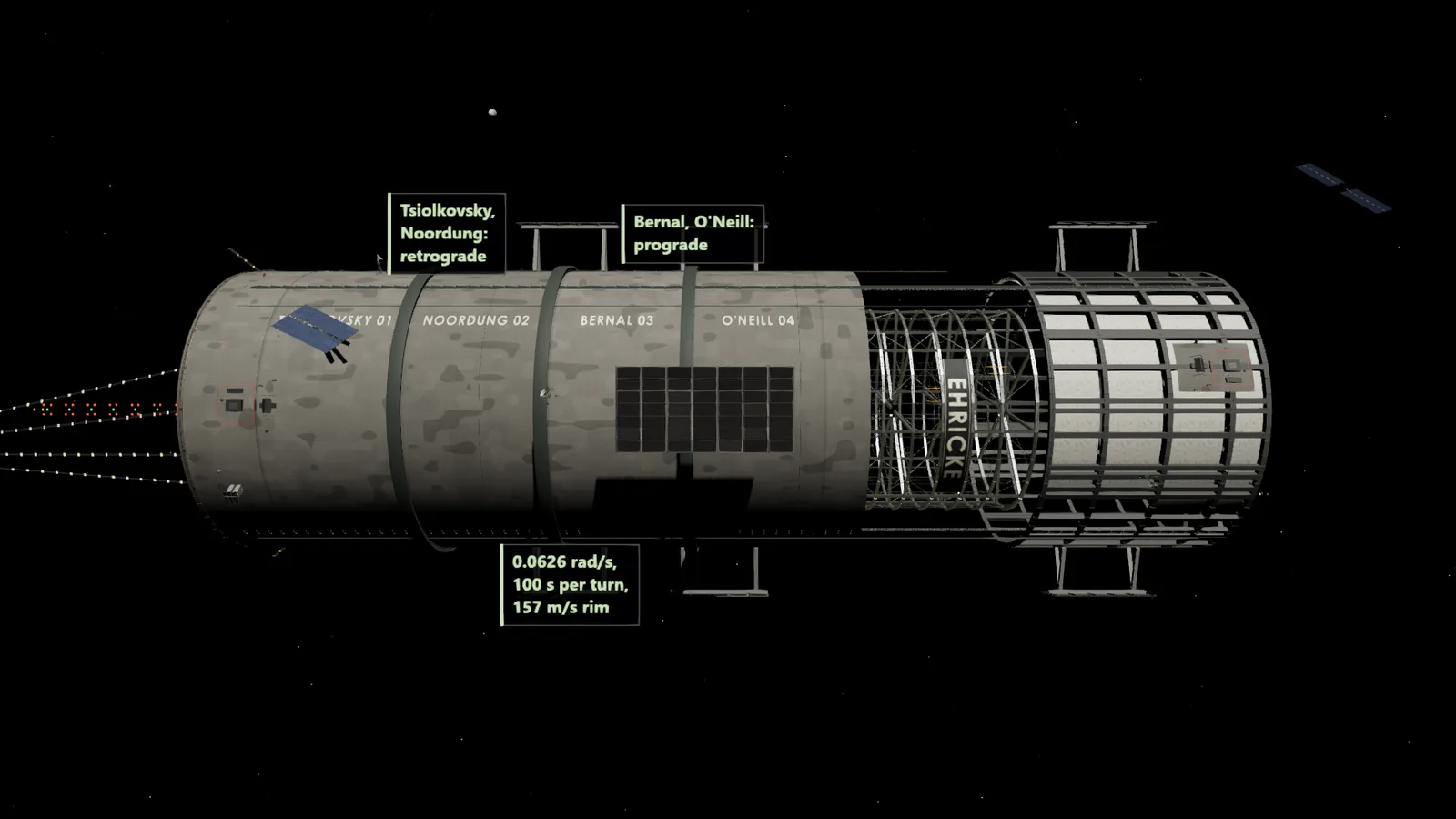
Concordia cancels the problem instead of fighting it. Seen from the spaceport end, Tsiolkovsky and Noordung (Rotors 1 and 2) turn one way (retrograde) and Bernal and O'Neill (Rotors 3 and 4) turn the other (prograde). Each spin pair holds half the total, one negative and one positive, so the habitation rotors add up to zero by construction. Design value
With the pairs balanced, steering the station by one degree per day takes about 4 kN, for a day to start the turn and a day to stop it. Without pairing it takes 4.5 MN. The pairs make steering about a thousand times cheaper. Established physics
All four rotors turn at the same rate and give the same 1 g. The only difference a resident can find is the direction of the Coriolis push, which points opposite ways in the two pairs. The ascender cabins lean opposite ways too.
Open in the simulation: Momentum overlay Open in the simulation: Rotational frame overlay Open in the simulation: Two spins, one steady station.
The industrial rotor and the momentum rings
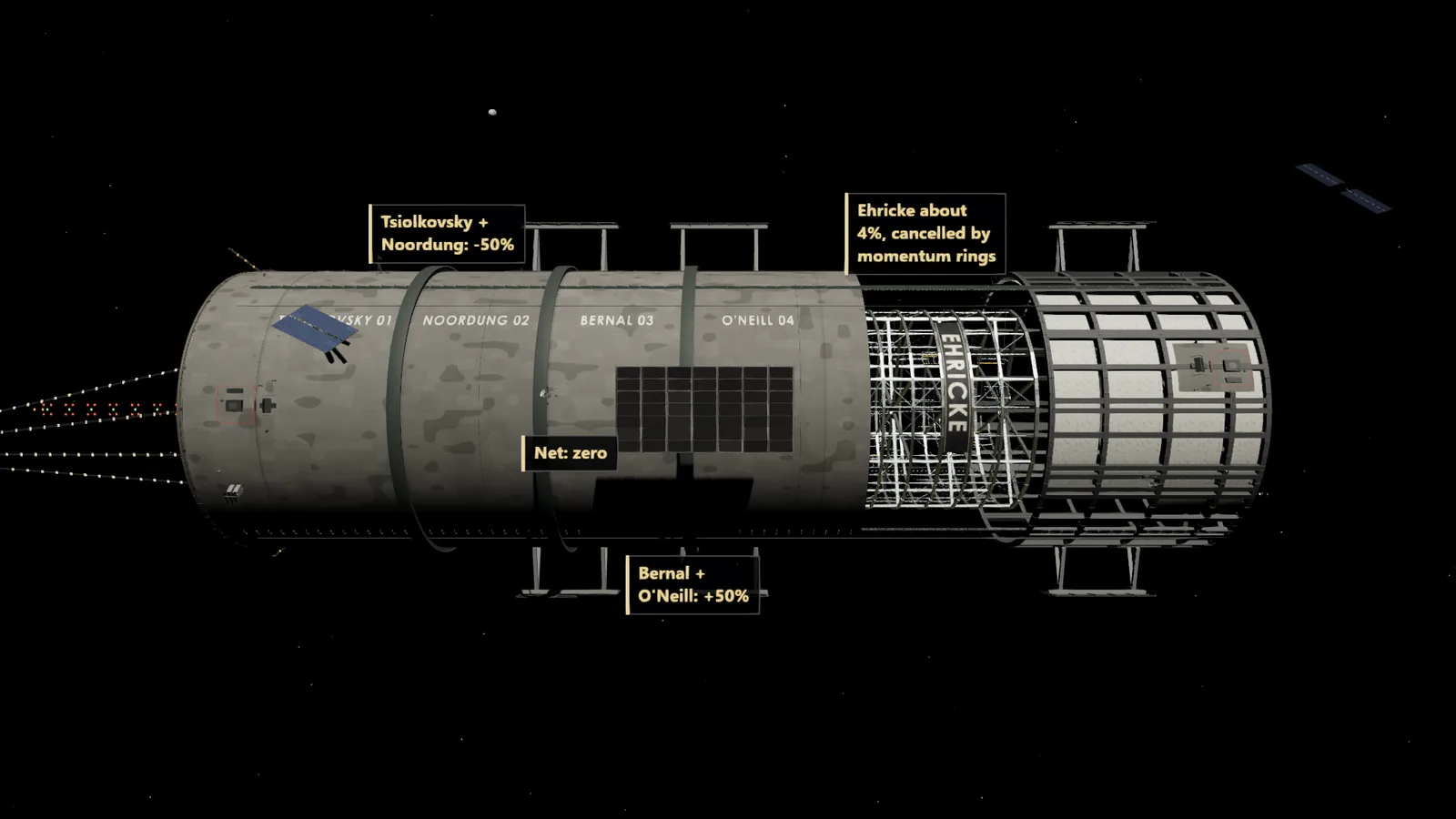
One more spinning body breaks the balance. The industrial rotor is 2,300 m in radius and 3,500 m long, and it turns once every 143 seconds. It spins the same way as rotors 1 and 2 and holds about 4 percent of the four-rotor total, 1.9 × 10¹⁶ newton-metre-seconds. Its outer edge has 0.45 g. Design value
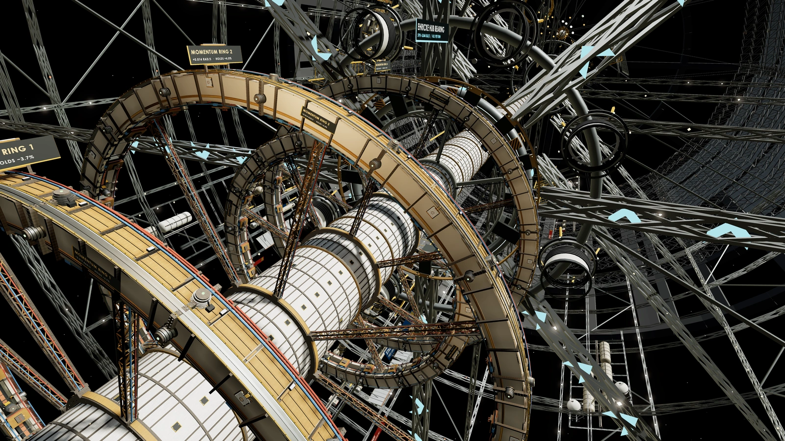
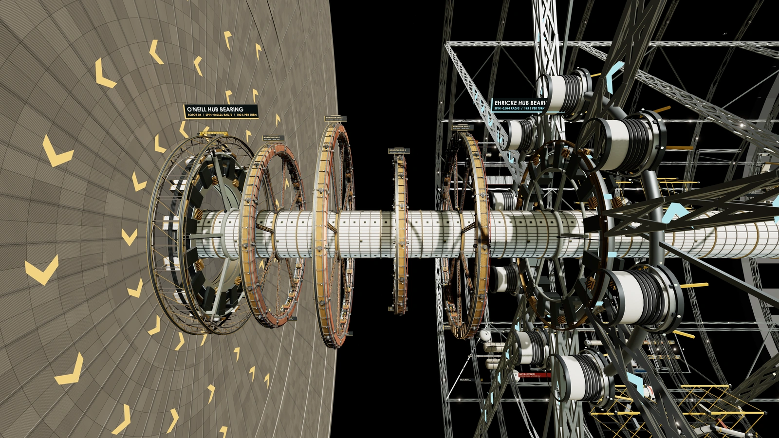
That 4 percent is cancelled by two momentum rings in a stationary vacuum bay between rotor 4 and the industrial rotor. Each is a carbon-fibre-class loop 3,000 m in radius, spinning in the opposite sense to the industrial rotor with its rim moving at 1 km/s. Together the rings weigh about 7 million tonnes, about 0.35 percent of the station. Engineering challenge
The rings speed up and slow down as the industrial mass changes. Cargo arrives, ships leave, rotor inventories shift, and the control system trades momentum between the rings and the rotors. It holds the net total within 0.1 percent of the four-rotor total. Nothing is thrown away. Momentum moves from one machine to another and the cost is electricity, not propellant. Design value
Bearings at the seams
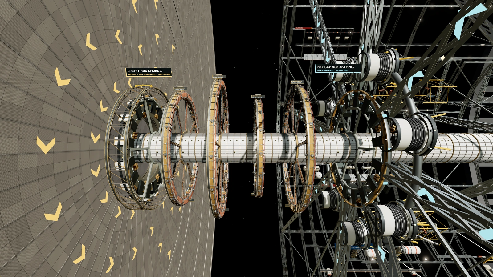
Rotors do not roll on wheels. Each one floats on magnetic bearings at both ends, with emergency catchers that never touch in normal operation. In the bearing gallery between rotor 4 and the industrial rotor, the two hubs turn against each other, one prograde and one retrograde. Engineering challenge
Between rotors 2 and 3 the end walls move past each other at 157 m/s in opposite directions, 313 m/s apart. No bridge can cross a gap like that. A stationary frame carries the utility trunks, and passengers cross by the axis: ascender to the hub, a spin-down through the spin lock, the spine, and a spin-up into the next rotor. Rotors in the same pair keep a fixed relative position, so passenger and freight bridges can cross the gap within a pair. Design value
What a resident notices
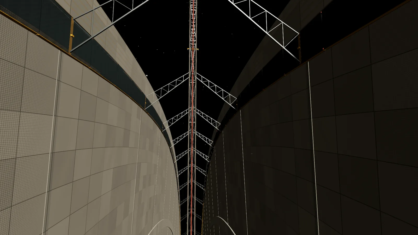
On the ground, nothing. Momentum is a bookkeeping problem for the axis. You meet it in three places: the closed end walls signed COUNTER-ROTATING, the bearing gallery with its two hubs turning opposite ways, and the momentum bay where the rings turn in their housings. The station still re-points slowly. Launches wait for scheduled windows rather than turning the station to suit one ship.
Try it
Move cargo, launch a ship or fill a rotor, and watch the ledger balance.
Go deeper: The numbers Established physics
Angular momentum of a spinning body is its moment of inertia times its spin rate. For a rotor with most of its mass near the rim:
L = I × ω ≈ m × r² × ω
Rotor: L = 3 × 10¹¹ kg × (2,500 m)² × 0.0626 rad/s = 1.17 × 10¹⁷ N·m·s
Four rotors, by magnitude: 4.7 × 10¹⁷ N·m·s
Industrial: L ≈ 1 × 10¹¹ kg × (2,070 m)² × 0.044 rad/s = 1.9 × 10¹⁶ N·m·s
| Body | Spin | Share of the four-rotor total |
|---|---|---|
| Rotors 1 and 2 | retrograde, 0.0626 rad/s | minus 50% |
| Rotors 3 and 4 | prograde, 0.0626 rad/s | plus 50% |
| Industrial rotor | retrograde, 0.044 rad/s | minus 4% |
| Momentum rings | prograde | plus 4% |
| Net | 0 (within 0.1%) |
The rotor mass is a planning value. The industrial rotor's effective radius is 0.9 of its 2,300 m outer radius because its mass is not all at the rim.
Go deeper: Worked example: the cost of steering Established physics
Turning a body with angular momentum L at a rate Ω needs a torque of Ω × L. Steering at 1 degree per day is Ω = 0.01745 rad / 86,400 s = 2.02 × 10⁻⁷ rad/s.
Unpaired: τ = 2.02 × 10⁻⁷ × 4.7 × 10¹⁷ = 9.5 × 10¹⁰ N·m
Force at each end of a 21 km hull: F = τ / 21,000 m = 4.5 MN
Paired, net held well inside 0.1%: F ≈ 4 kN
Pairing cuts the force by a factor of 1,000. The remaining 4 kN is a tiny push for the station's thrusters and momentum rings.
An ascender also moves momentum. Each ascent hands the rotor about 2.1 × 10¹⁰ N·m·s, roughly 2 parts in 10 million of one rotor's total. A climbing cabin's partner descends on the same tower and takes the momentum straight back.
Go deeper: Sizing a momentum ring Established physics
A ring of mass m, radius r and rim speed v holds L = m × v × r. To hold 1.9 × 10¹⁶ N·m·s at r = 3,000 m and v = 1,000 m/s:
m = L / (v × r) = 1.9 × 10¹⁶ / (1,000 × 3,000) = 6.3 × 10⁹ kg
σ = ρ × v² = 1,600 kg/m³ × (1,000 m/s)² = 1.6 GPa
That is 6.3 million tonnes, or about 7 million tonnes with trim headroom, split between two rings of about 3.5 million tonnes each. Against the station's 2.05 billion tonnes, 7 million tonnes is 0.34 percent, about 0.35. The hoop stress ρv² sets the speed limit, because a faster rim would need a stronger material than carbon fibre.
Sources and further reading
Real-world sources
- Gerard K. O'Neill, "The Colonization of Space", Physics Today 27(9), September 1974: physicstoday.aip.org/features/the-colonization-of-space.
- Gerard K. O'Neill, The High Frontier: Human Colonies in Space, 1976. Its cylinder design, Island Three, pairs two cylinders rotating in opposite directions to cancel gyroscopic effects: en.wikipedia.org/wiki/O'Neill_cylinder.
Concordia design documents
- Concordia engineering specification, section 16, and the counter-rotation design note.