Holding in the air
Blow up a balloon and the rubber stretches. The air pushes outward on every patch of skin, and the skin pulls back along its own surface. A barrel works the same way: hoops around the staves stay in tension so the staves cannot spring apart. Engineers call that tension hoop stress, and any vessel that holds pressure carries it.
At sea-level pressure every square metre of wall holds back about 10 tonnes of force. A rotor floor covers 39 km², and the air pushes on it with the force of 400 million tonnes. Established physics The pressure vessel that holds this is not a thin metal can. It is a composite tension structure: a gas-tight membrane, a ring of high-strength tension bands, axial members that tie the ends together, and pressure end caps. Airtightness and strength are separate jobs. If one band fails, the others take the load and the failure does not spread. Engineering challenge
The vessel sits hundreds of metres inside the outer skin of the station. A hit on the skin never reaches the air.
The weight of a city
The air is only part of the load. Everything standing on the ground also pushes outward, because in a rotor weight is centrifugal force. The ground, the buildings, the lakes and the trees add up to a few hundred billion kg per rotor, and each kilogram presses on the wall with a full Earth gravity. Established physics
Nothing rests on wheels. The centrifugal loads are all internal to the spinning rotor. The stationary structure around it only aligns the rotor, damps its wobble and passes utilities across the gaps. The rotors are not bolted to the hull; they float on magnetic bearings. Engineering challenge
The megaframe
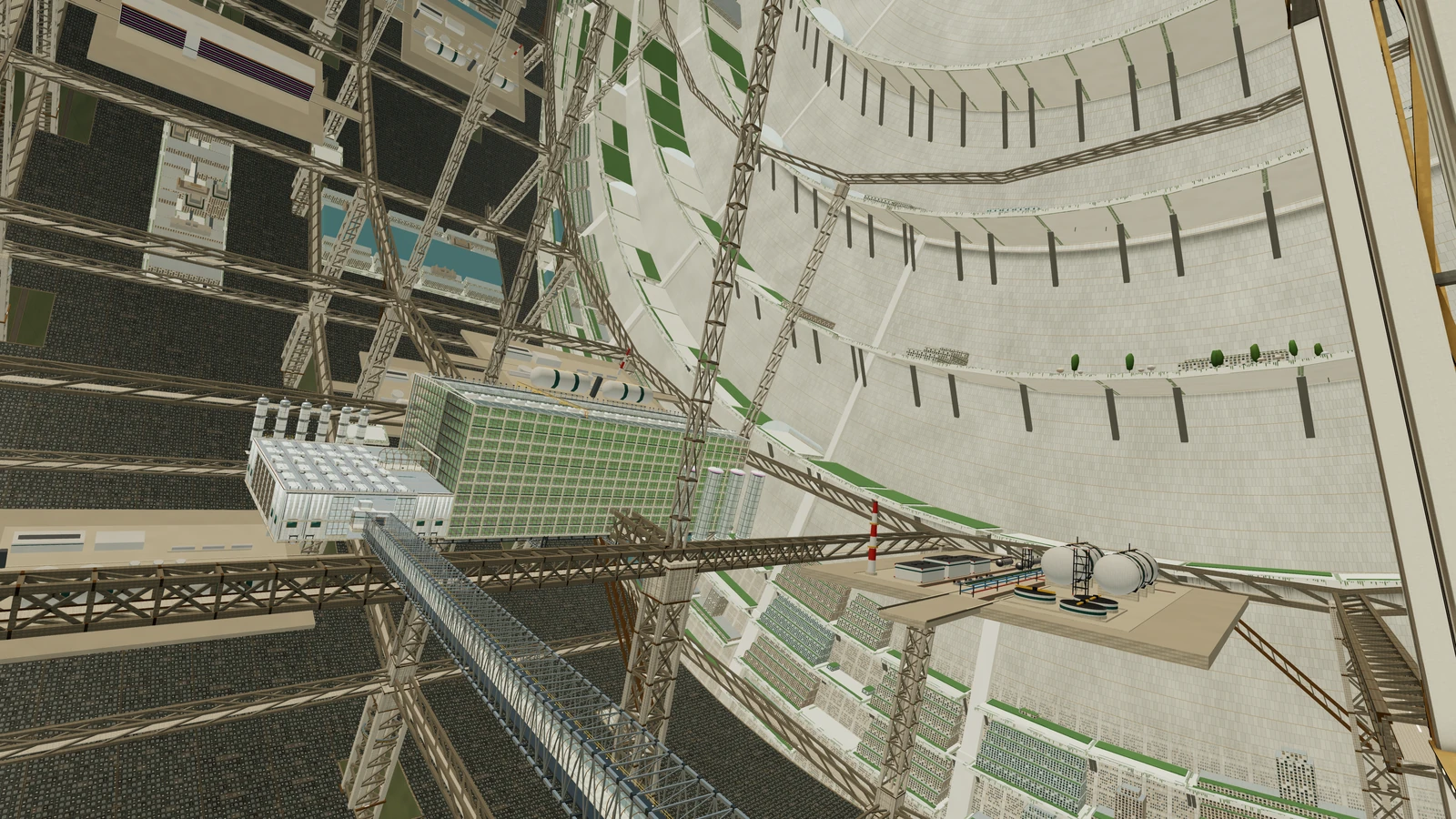
Above the ground, the city does not hang from the sky. A three-dimensional lattice called the megaframe rises from the ground as far as 1,500 m up. Its ribs, ring beams at 625, 1,000 and 1,500 m, and axial members divide each rotor into 24 cells. Bays are 654 m around and 480 m long. Streets, plates and bridges fill the spaces between. Design value
The frame is built before the city, while the rotor is stationary and gravity is low, and is engineered for full operating loads. Every permanent building load passes from the building to a bay structure, to the megaframe, to the rotor's tension bands.
The frame thins as it climbs because weight does. A tonne at the ground weighs 9.8 kN. At 1,500 m up it weighs 3.9 kN. Piers are about 45 m square up to 625 m, 28 m square to 1,000 m and 15 m square to 1,500 m. The whole frame weighs about 6 million tonnes per rotor, 150 kg per square metre of floor, about fifty times lighter than the same volume built solid. Design value
Open in the simulation: Structural overlay at the megaframe base Open in the simulation: Mid-Gravity Megaframe Open in the simulation: Pressure overlay
End walls
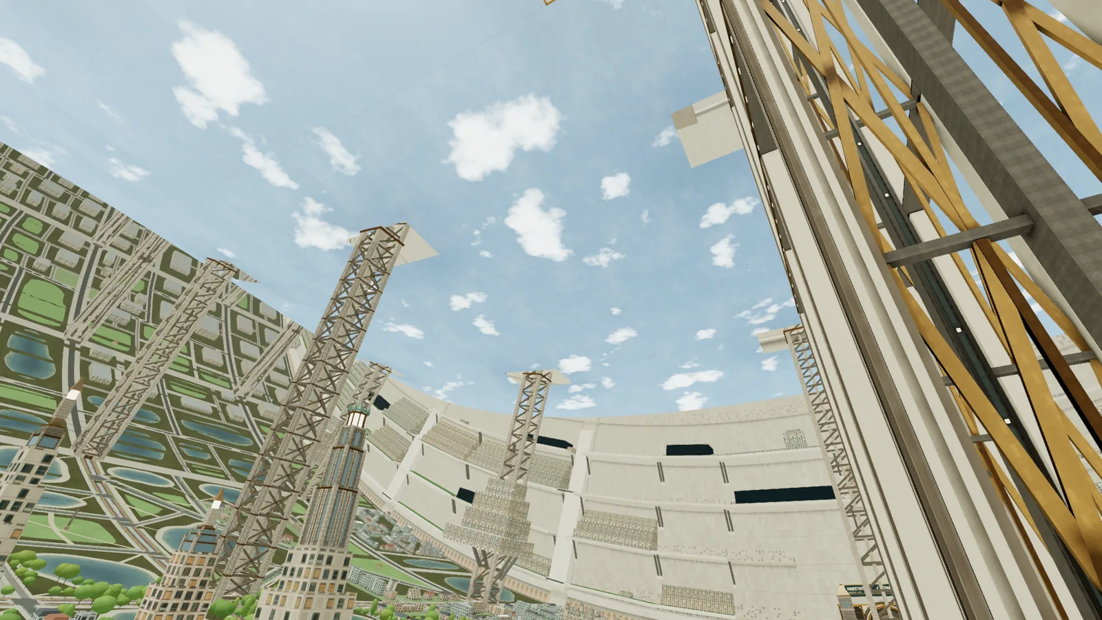
Each rotor ends in a wall that is also a place to live. From the ground at 2,500 m radius to the 64 m bore at the axis, an end wall is an inhabited cliff 2,436 m tall. Gravity on the wall follows the same line as everywhere else: 1 g at the foot, 0.6 g at 1,000 m, almost nothing at the top. The 24 cells are 654 m wide at the rim and 131 m wide at 2,000 m up. Most of the wall is near the ground: 64 percent of its area lies in the first 1,000 m. Design value
An end wall also has a job. It holds back the air. At sea-level pressure, the push on one end of one rotor is about 2 trillion newtons, equal to the weight of 200 million tonnes. Established physics
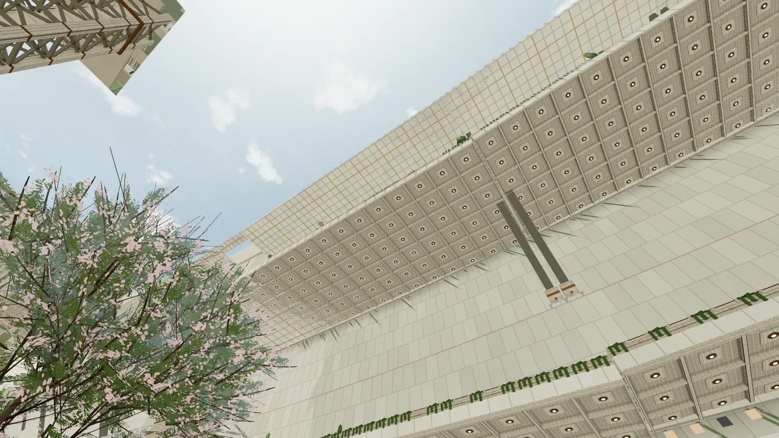
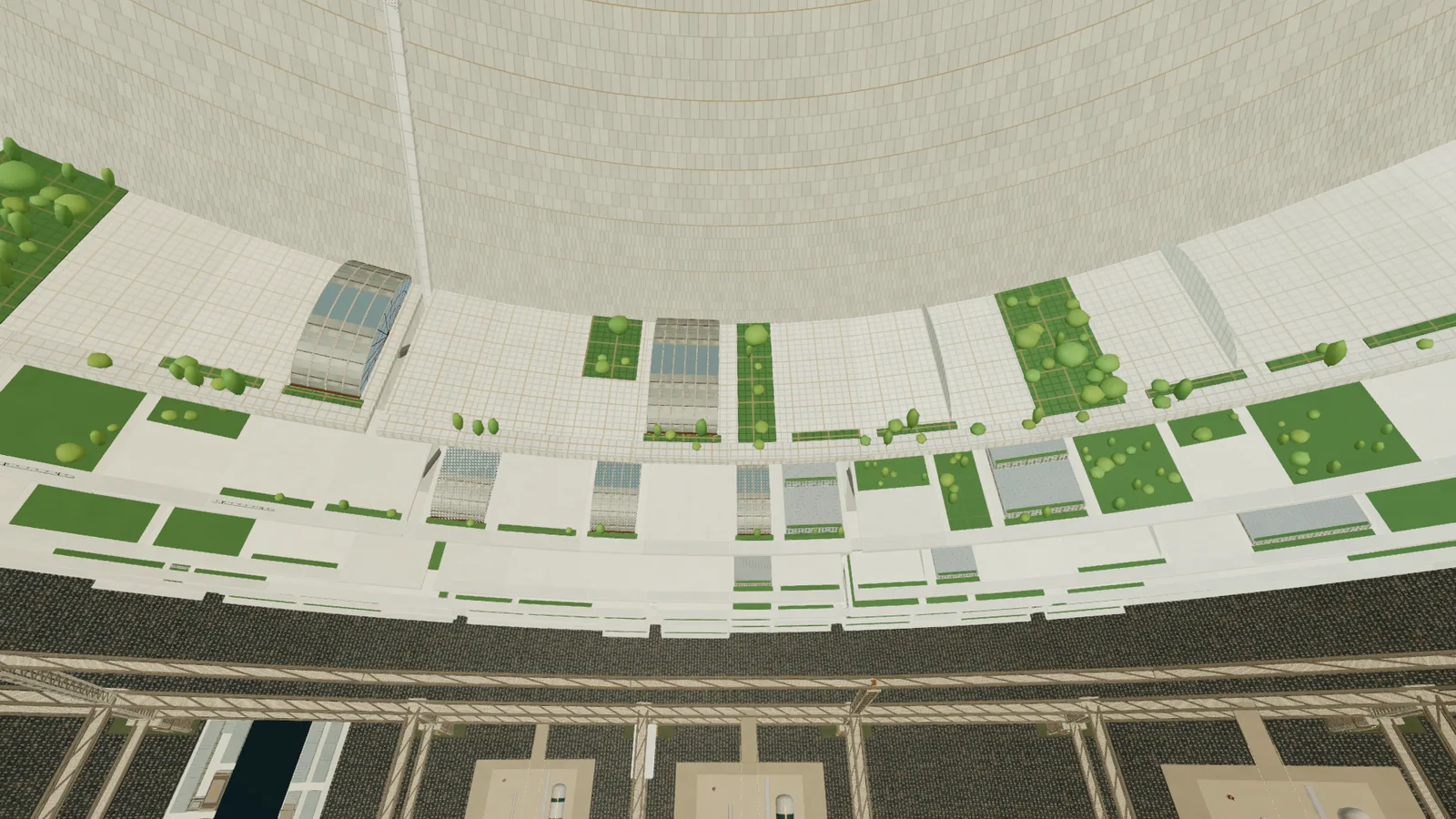
Open in the simulation: End Wall: Foot of the Cliff Open in the simulation: End Wall: Upper Wall from the Axis Side
The stationary shell
Around the rotors sits a second, stationary structure 21 km long and 6.2 km across. It is a deep open truss that carries removable shielding cassettes, radiators, launch tracks, docks and antennas. It does not hold pressure. A punctured shielding panel loses mass and nothing else. Design value Safety compares this with the 1970s designs.
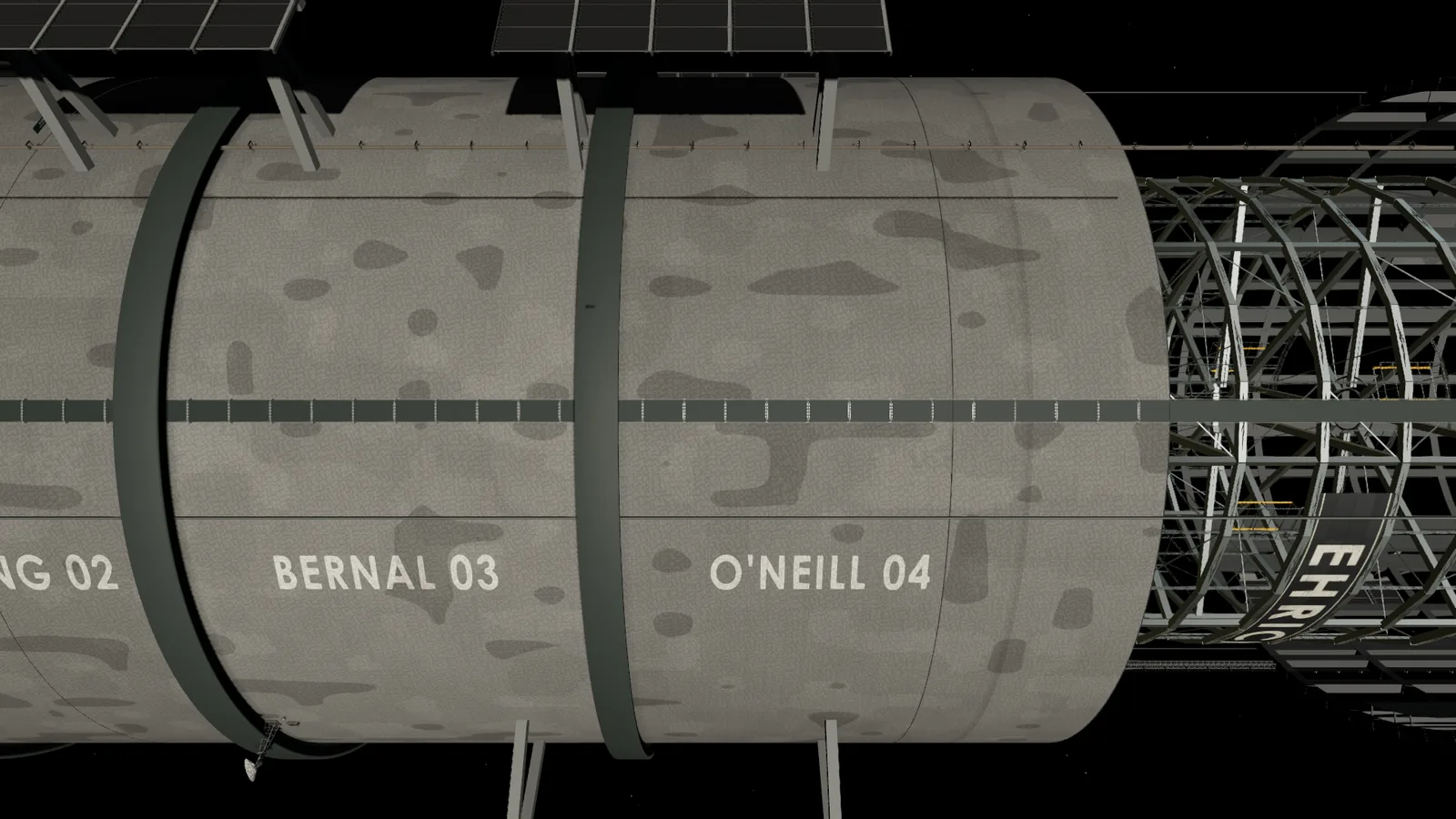
The stationary spine along the axis is the exception. It is a 120 m tube at one atmosphere, and its walls carry a hoop load of 6 MN per metre. The thickness of its aluminium-lithium shell is a design estimate of about 60 mm. Design value Shielding and debris protection are on radiation and debris.
What it feels like
You almost never see the structure. The shell is opaque and the rotor wall lies under the city. What you see is the megaframe: pale ribs of sintered regolith composite rise from the neighbourhoods, big, regular and a little monumental. Newer buildings fill the gaps in many styles. At the end walls the structure becomes the landscape. A cliff of terraces climbs into the air until it narrows to the axis.
Each rotor was brought to speed in small steps over days to weeks, pausing at each one to look for resonances. Story Building Concordia tells that story.
Go deeper: Loads on the rotor wall Established physics
For a thin-walled cylinder of radius r, wall thickness t and internal pressure P, the hoop stress is σ = P × r / t. The pull per metre of cylinder length is what the wall must carry, whatever its thickness:
N_air = P × r = 101,325 Pa × 2,500 m = 2.53 × 10⁸ N/m
Weight adds a second load. With a planning mass of 3 × 10¹¹ kg per rotor, of which about 4.5 × 10¹⁰ kg is air (the air is already counted in the pressure), the rest is 2.55 × 10¹¹ kg spread along 2,500 m:
mass per metre = 2.55 × 10¹¹ / 2,500 = 1.02 × 10⁸ kg/m
radial force = 1.02 × 10⁸ × 9.8 = 1.0 × 10⁹ N/m
N_weight = 1.0 × 10⁹ / 2π = 1.6 × 10⁸ N/m
N_total ≈ 410 MN/m
Material decides the mass. A tension band working at an assumed 500 MPa needs 410 / 500 = 0.82 m² of cross-section per metre of length. The ring is 15,708 m around. Per metre of rotor length:
| Material | Density | Band mass |
|---|---|---|
| Steel | 7,800 kg/m³ | 100,000 t |
| Carbon-fibre-class composite | 1,600 kg/m³ | 21,000 t |
Over the 2,500 m of one rotor, steel would need 250 million tonnes, nearly the 300 million tonnes the whole rotor is planned to weigh. Four rotors of steel bands would be 1,000 million tonnes, about half of the station. A composite needs 52 million tonnes per rotor. That gap is why the bands are composites.
The 500 MPa working stress is an illustration. Real bands are sized with margins and redundancy.
Go deeper: Why the megaframe thins with height Established physics
Weight at radius r is m × ω² × r, so it falls with height h above the ground:
g(h) = (2,500 − h) / 2,500 × 1 g
cantilever limit: L_max = 40 m / g
A plate can reach 40 m out from a pier at 1 g and 100 m at 0.4 g. Fewer, thinner piers carry lighter loads higher up. The design axial load at a pier base is about 2 GN, and a primary pier weighs about 20 kt. These are design estimates for the original frame.
Go deeper: The force on an end wall Established physics
An end cap is a disc of radius 2,500 m with air pushing on it:
F = P × π × r² = 101,325 × π × 2,500² = 1.99 × 10¹² N
F / g = 2.0 × 10¹¹ kg, or 200 million tonnes-force
Each end carries that load back into the tension bands and axial members. The end caps are among the largest pressure-bearing surfaces ever built, and the city uses their inner faces as living space.
Sources and further reading
Real-world sources
- Gerard K. O'Neill, "The Colonization of Space", Physics Today 27(9), September 1974: physicstoday.aip.org/features/the-colonization-of-space.
- Richard D. Johnson and Charles Holbrow (eds.), Space Settlements: A Design Study, NASA SP-413, 1977: ntrs.nasa.gov/citations/19770014162.
- Thin-walled pressure vessel hoop stress, σ = P r / t: en.wikipedia.org/wiki/Cylinder_stress.
Concordia design documents
- Concordia engineering specification, sections 6 to 17, and the megaframe and end-wall design notes.