What you see
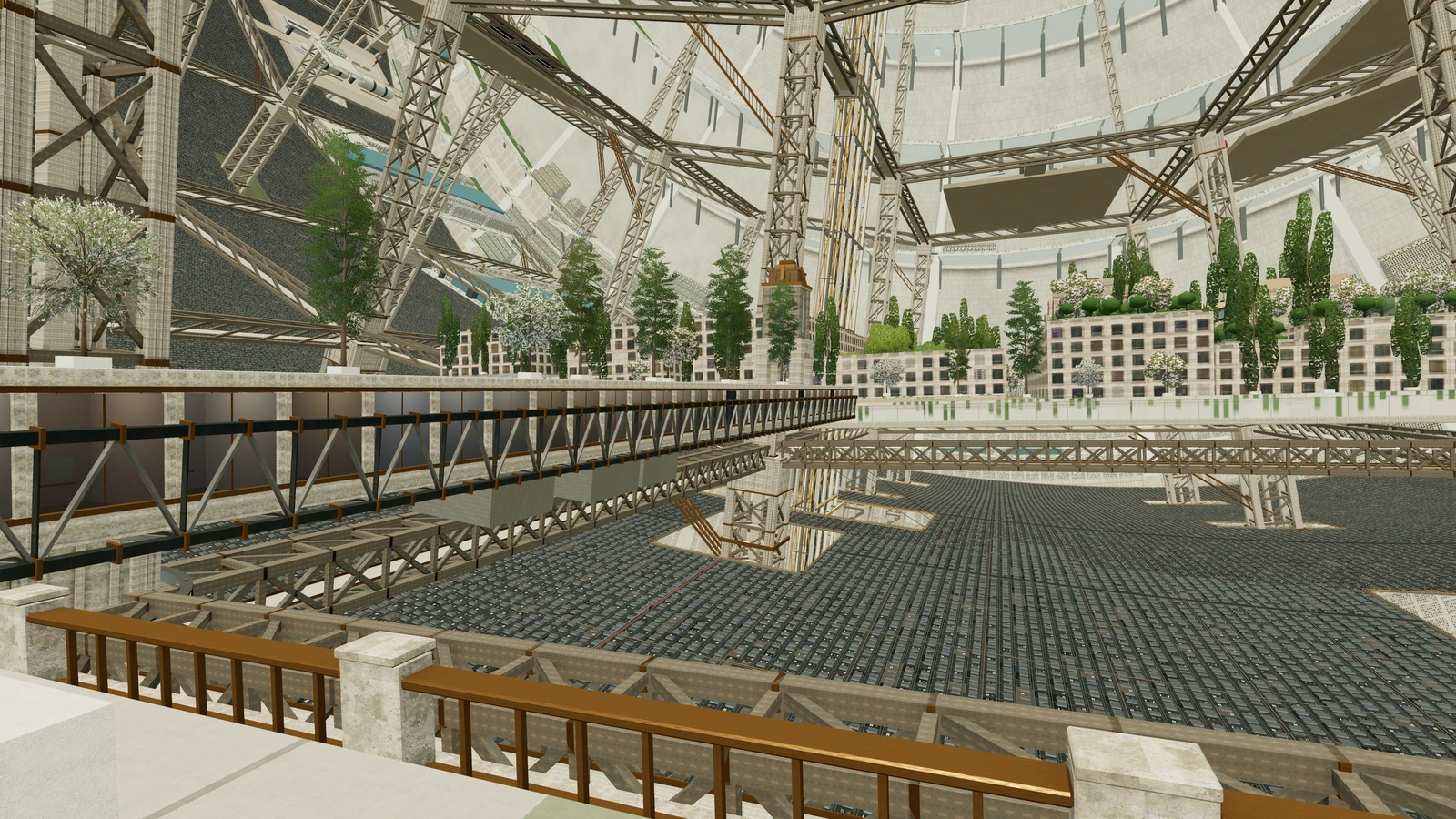
The frame is pale sintered regolith and steel. Primary piers stand on the ground, 45 m square at the base, and rise toward the axis in three stages, with ring beams at 625 m, 1,000 m and 1,500 m. Between them, bays 654 m around and 480 m along the rotor hold plates, atria and inhabited bridges.
On a plate at 625 m you weigh about three quarters of your ground weight. Housing, offices, universities and hotels fill the plates up to about 800 m. Higher up, the frame turns to service halls, farms and process vaults, covered in Upper city farms. Balconies reach further as gravity drops: 40 m at 1 g, 100 m at 0.4 g.
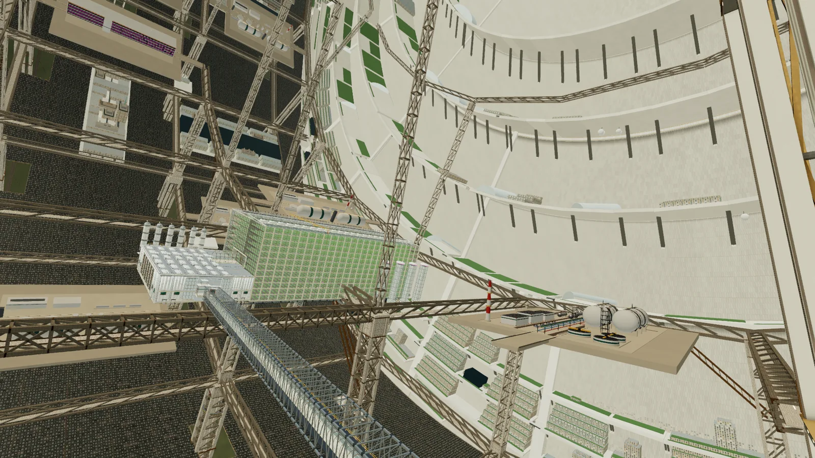
The oldest parts of the frame are monumental and repetitive, with large joints and a restrained Art Deco look. Newer infill is organic: retrofits, bridges and converted spaces added over the years since the first residents arrived. Towers wear crowns and spires, and the tallest ones on the plates carry beacons. Nothing on the ground reaches through the sky. Inhabited bridges join the plates, with gate towers at their ends, and on the flat roofs sit penthouses, cooling towers, dishes and glasshouse pavilions. From the street you see only the foot of a pier rising into the sky. The plates sit above the artificial sky, so the second city is hidden from the streets below. From a plate, the upper city on the far side of the rotor hangs overhead.
The end walls
Each rotor ends in a disc, and the disc is a city face. The end wall is an inhabited cliff 2,436 m tall, from the ground to the 64 m bore at the axis. Its 24 cells are 654 m wide at the rim and narrow to 131 m at 2,000 m of height. Ledges, viaducts and terraces step up the face, with trains on the track strips.
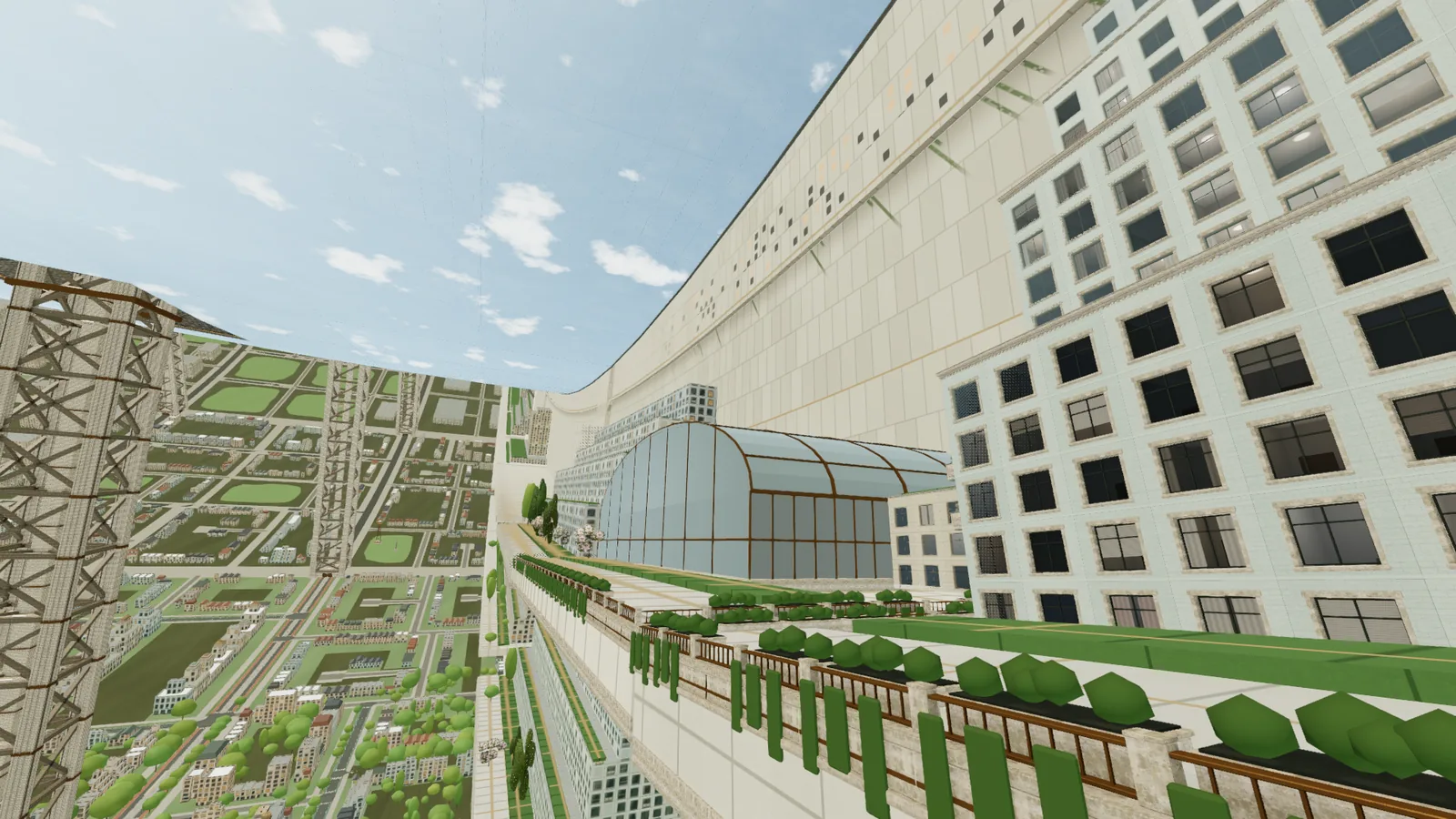
Most of the face is near the ground: 64 percent of the disc area lies in the outer 1,000 m of height, so the cliff is broad at the foot and narrows like a tower toward the axis. Low-gravity halls, vaults and gardens fill the upper ring ledges, where the ribs thin toward the bore.
Gravity follows the same rule as everywhere: it falls in a straight line with height. The viaduct terrace at 241 m is at about 0.9 g. Two walls are closed: the forward wall of Noordung (Rotor 2) and the aft wall of Bernal (Rotor 3) face each other across the counter-rotating gap, and they are signed COUNTER-ROTATING / CROSS VIA AXIAL SPINE.
How it works in brief
The frame is a load path. Every building rests on its bay structure, the bay on the primary frame, and the frame on the rotor's outer tension structure. All permanent loads go outward, because outward is down. Structure explains the pressure vessel, hoop stress and the frame in detail.
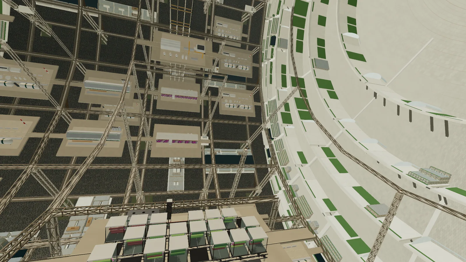
Because the frame was built while the rotor stood still but was designed for full spin, the city could be filled in over time. Try the overlay: Open in the simulation: Structural overlay
Key numbers
Go deeper: Piers, beams and gravity
Pier size shrinks as the load above it shrinks. These are the design values: 45 m square up to 625 m, 28 m square up to 1,000 m, and 15 m square up to 1,500 m. The load at the base of a primary pier is about 2 GN. The whole frame is about 6 million tonnes per rotor, roughly 150 kg per square metre of floor, about fifty times lighter than the same volume built solid. Axial members run every 480 m.
| Level | Height | Gravity |
|---|---|---|
| First ring beam | 625 m | 0.75 g |
| Second ring beam | 1,000 m | 0.60 g |
| Third ring beam | 1,500 m | 0.40 g |
Gravity at height h above the ground is g = 1 − h / 2,500 m.
Visit
Open in the simulation: Urban Megaframe Base Open in the simulation: Mid-Gravity Megaframe Open in the simulation: Megaframe Plate District Open in the simulation: End Wall: Foot of the Cliff Open in the simulation: End Wall: Viaduct Terrace Open in the simulation: End Wall: Upper Wall from the Axis Side
Nearby
Arbor Quarter
Arbor Quarter is a neighbourhood on the floor of Tsiolkovsky (Rotor 1), where the ground weighs what it does on Earth.
Ascenders and the sky
The ascender is a lift 2.4 km tall. It carries 150 people from the street through the artificial sky to the axis in about ten minutes, and on the way your weight drops to almost...
Upper city farms
Food is grown high in each rotor, where gravity is 0.6 g and the air is the same air the city breathes.