What you see
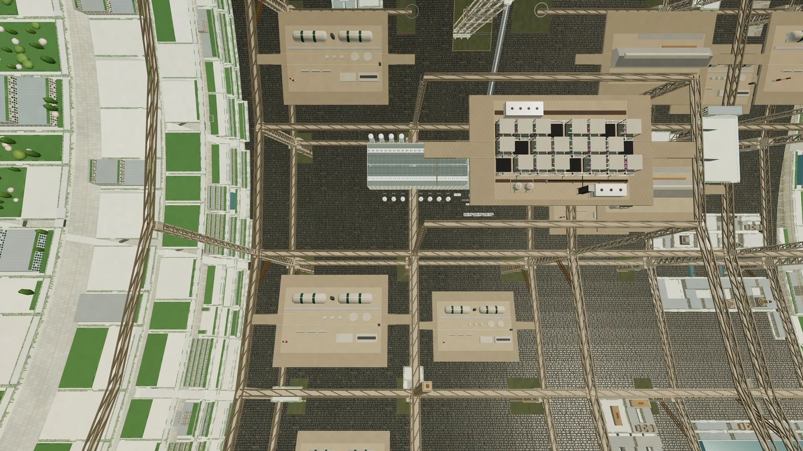
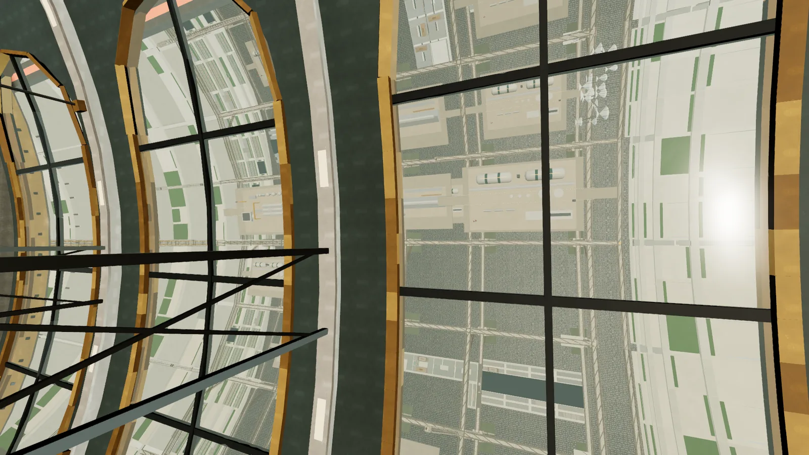
The ascender ends at a hub: a drum 66 to 140 m in radius and 150 m long, turning with the rotor, with four tower portals marked by bronze sunbursts. Beyond a bearing collar is the spine, which never rotates. From the spine's windows the city turns past you once every 100 seconds, while the spine stays still.
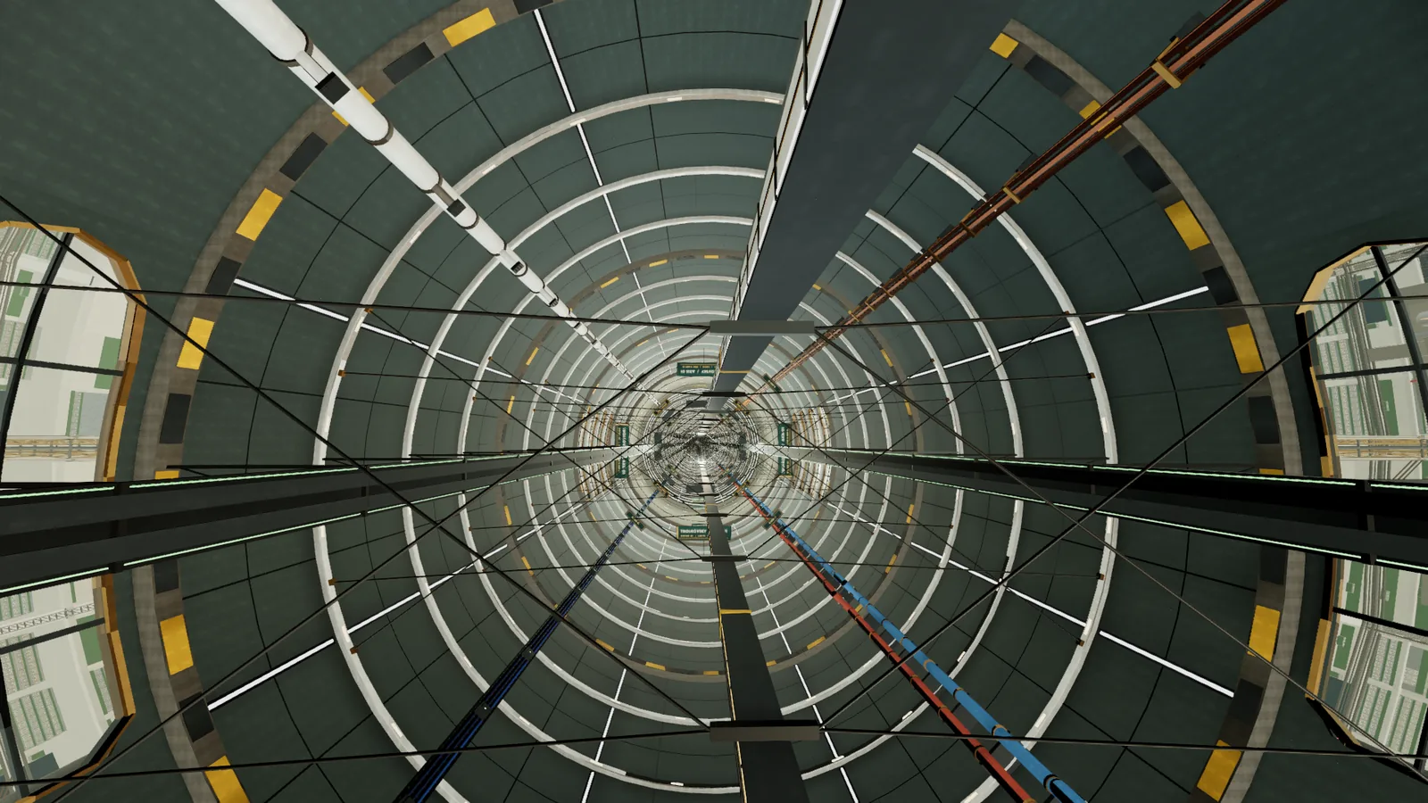
The spine is a pressurized tube 120 m across at about 1 atm, built in 199 segments of 100 m. Inside it run frames and ring lamps every 25 m, the express guideway on its stays, crew galleries, four power and utility trunks and boards reading AXIS 01. It runs from the aft terminus at the back of the station to the spaceport at the front. Pressure refuge capsules sit along the tube, each with a hatch, a handwheel and an amber beacon.
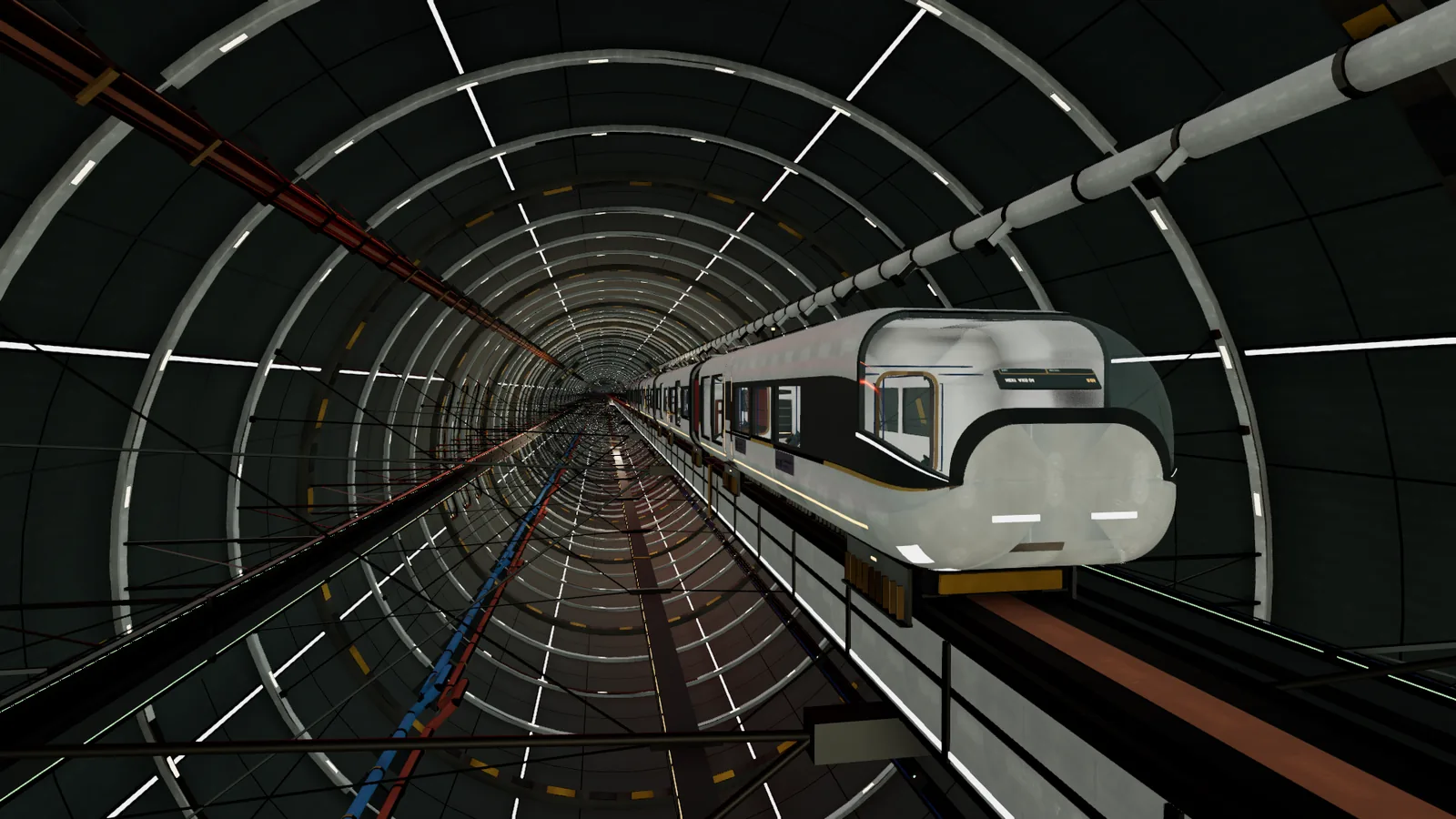
The express is a five-car train on a magnetic guideway. Its cars are 25 m long and carry passengers in restraint couches, 24 to a car, with handholds and panoramic windows. It runs at 140 m/s.
Inside a car, restraint couches line the four wall quarters, with grab rails and poles, net-door lockers and a live destination display over the end door. A panoramic bay has a full-height side window and a roof light onto the spine.
Changing frames
You cannot step from a rotating floor onto a still platform. The hub has a spin-decoupling lock: eight chambers, each 90 m long, on a magnetic-bearing carousel. A chamber fills with passengers, spins down over 96 seconds, latches to the spine, and opens into zero g. For the other direction it spins up. A full cycle takes about ten minutes.
Open in the simulation: Spin-Decoupling Lock, Tsiolkovsky Open in the simulation: Ascender: Rotating Transfer Hub
The lock is how passengers cross between rotors that turn in opposite directions. See Counter-rotation for the reasoning and Moving around for the transfer.
Bridges and the gap
Tsiolkovsky and Noordung (Rotors 1 and 2) turn the same way, as do Bernal and O'Neill (Rotors 3 and 4). Within a pair, a rotating bridge crosses the 300 m gap: a through-truss tube 25 m in radius, with a promenade, a transit lane, window bands and a telescoping middle that retracts before the rotors change speed.
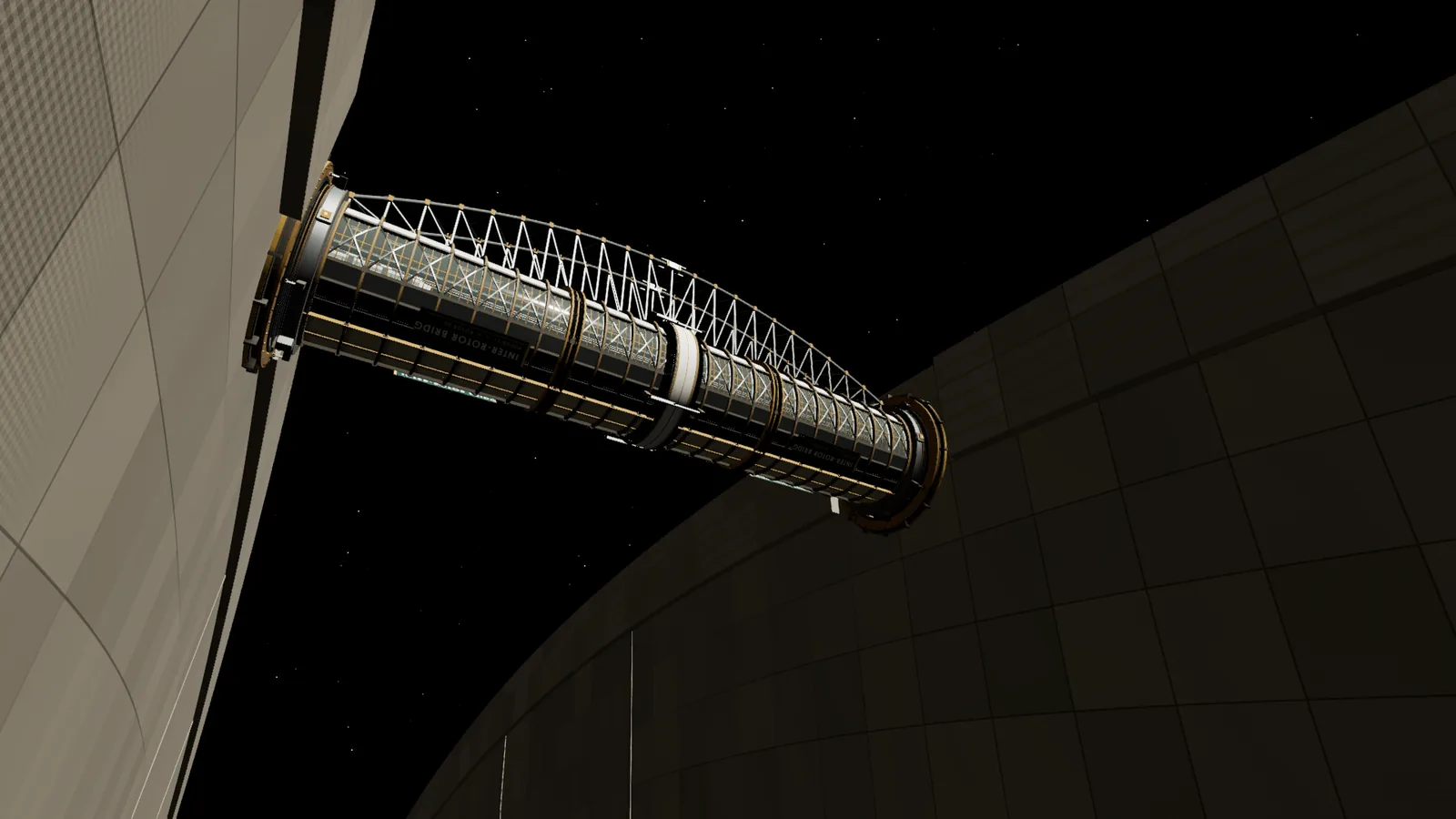
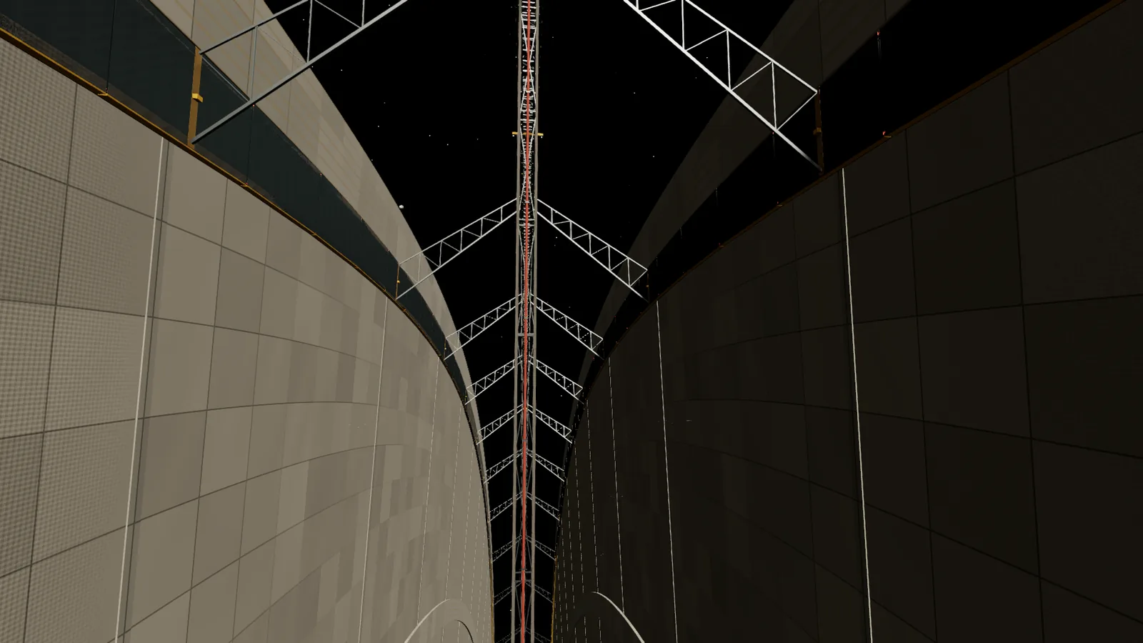
Between rotors 2 and 3 there is no bridge. The two end walls move in opposite directions at about 157 m/s each, 313 m/s relative to each other. A stationary service frame hangs in the gap on non-contact slip seals, carrying 24 utility trunks across. Passengers go through the spine. Walls facing the gap are signed COUNTER-ROTATING / CROSS VIA AXIAL SPINE.
Open in the simulation: Counter-Rotating Interface, Noordung and Bernal Open in the simulation: Inter-Rotor Bridge 01, Deck
Key numbers
Go deeper: Frames, bearings and the hub
The hub terminal sits at a radius of 70 m, where gravity is 0.028 g; the hub skin at 140 m is 0.056 g. The lock spins down at a constant angular acceleration, so apparent gravity in the chambers stays under 0.0025 g. Each chamber is 90 × 10 × 3.3 m, and the seals are ferrofluid labyrinths. One full cycle of spin-down, latching and spin-up takes 602.2 s.
The spine shell is about 60 mm of aluminium-lithium. At 1 atm its hoop load is 6.0 MN/m, and each segment weighs about 6,100 t. The spine holds no structural load for the rotors. It carries passenger and freight transport, power trunks, comms, thermal-transfer equipment, emergency services and access to industry.
The bridge tube is 300 m between end walls, centred 45 m above the ground at 0.98 g. Its lower truss is 40 m deep at mid span. The mid-span telescope and gimbal rings at both ends take up the rotors' motion.
Visit
Open in the simulation: Stationary Axis: City Rotating Around Viewer Open in the simulation: Axial Spine: Interior Open in the simulation: Axial Spine: Observation Windows Open in the simulation: Axial Express · Interior Open in the simulation: Inter-Rotor Bridge 01, Outside Open in the simulation: Inter-Rotor Service Gap
Nearby
Ascenders and the sky
The ascender is a lift 2.4 km tall. It carries 150 people from the street through the artificial sky to the axis in about ten minutes, and on the way your weight drops to almost...
The industrial rotor
Ehricke, the industrial rotor, is the factory floor. It is a skeleton of rings and girders 3.5 km long, turning opposite the city rotors, with refineries, tank farms, container...
The spaceport
Everyone who arrives from Earth or the Moon comes through the spaceport at the forward end.
Aft works
The back of the station is where the electricity comes in. Eight tethers run 7 km aft to the solar farm, four masts land the power, two reactors can restart everything after a...